On the 3D Model tab, Work Features panel, use Point or Grounded Point in a part file to select model vertices, edge and axis intersections, intersections of three nonparallel faces or planes, and other work features as work points. You can also create work points as input to other work feature commands that require you to select a point.
In an assembly file, use the Point commands on the 3D Model tab. Work points can be created at the intersection of part faces, edges, vertices, and work geometry that span hierarchical levels in the assembly.
Work points can be placed on holes and cuts in part faces, model surfaces, construction surfaces, and base surfaces. When Loop Select Mode is active, you can place a work point on one or more closed loops.
Tip: To understand geometric dependencies, right-click a work feature in the browser or the graphics window, and then select Show Inputs. For example, you can right-click a work point to highlight the geometry from which it was created, such as a work axis and a work plane.
Work features are abstract construction geometry used when geometry is insufficient for creating and positioning new features. To fix position and shape, constrain features to work features.
Work points can be placed or projected onto part faces, linear edges, or onto an arc or circle. Work points can be constrained to the center points of arcs, circles, and ellipses.
Uses for work points
- Mark shaft and pattern centers
- Define coordinate systems
- Define planes (three points)
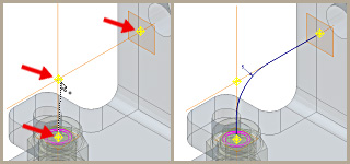
- Define 3D paths
When creating 3D sweeps, you can place a work point at the intersection of work axes and work planes. You click work points and vertices of existing parts to define the path of the sweep.
Differences in ungrounded and grounded work points
Grounded work points have all degrees of freedom removed and are therefore fixed in space. An ungrounded work point can be repositioned by dimensions or constraints.
In a part file, use the Grounded Point command. When you create a grounded work point in a part file, the 3D Move/Rotate command is available so that you can specify certain operations relative to the grounded work point. Or, use the 3D Move/Rotate option on the context menu later to reposition the work point.
In an assembly, you first create a work point, right-click, and then select Grounded from the context menu. The 3D Move/Rotate command is not available in an assembly file.
Position of grounded work point
To ground a work point in a part file, select it in the browser, right-click, and then select Ground.
- The work point position is originally determined by the geometry you selected to create it. When you select Ground, the relationship to the selection geometry is removed. The work point remains fixed in space, even if the selection geometry is moved or resized.If you clear the check mark on the Ground menu option, the associative relationship is restored. Changes to the selection geometry reposition the work point.
- When you use 3D Move/Rotate to edit a grounded work point, the relationship to the original selection geometry is permanently removed. You cannot restore an associative relationship to the original geometry used to create the work point.
When you use Grounded Work Point on the 3D Model tab, the created work point has no association to other geometry. It is fixed on the X, Y, and Z coordinates used to create it.
Changes to grounded work point
In a part file, right-click the grounded work point in the browser, and then choose one of the following options:
- Select the 3D Move/Rotate option.If geometry was used to position the work point, it is no longer associated to the work point. The work point remains grounded.
- Select the Redefine Feature option.The work point becomes associative to new geometry that you select. Changes to the geometry reposition the work point.


.gif)
0 comments:
Post a Comment