Work features are abstract construction geometry that you can use to create and position new features when other geometry is insufficient. To fix position and shape, constrain features to work features.
Overview of work features
Work features include work planes, work axes, and work points. The proper orientation and constraint conditions are inferred from the geometry you select and the order in which you select it.
The work feature commands provide on-screen prompts to help you with selection and placement. You can:
- Create and use work features in the part, assembly, sheet metal, and 3D sketch environments.
- Use and refer to work features in the drawing environment.
- Project work features into a 2D sketch.
- Create in-line work features to help you define a 3D sketch or position a part or assembly feature.
- Make work features adaptive.
- Turn the visibility of work features on or off.
- Drag to resize work planes and work axes.
Adaptive work features
Use adaptive work features to model relationships between geometric features and components in an assembly.
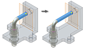
In the illustration, the work plane created in the tube part file is constrained to the face of another part. Even though the work plane "belongs" to the tube part file, it is not dependent on any tube geometry.
The tube end terminates on the work plane offset from the part face. The work plane in the tube part is adaptive because it allows the tube length to change if the associated face moves.
Adaptive and nonadaptive work features
Both adaptive and nonadaptive work features can be:
- Created in a part.
- Used for construction operations such as termination planes or sketch planes for new features.
An adaptive work feature is not constrained to geometry and can be positioned relative to other part geometry. A nonadaptive work feature maintains a constant relationship with the geometry used to create it, such as an offset distance.
In an assembly, a work feature is adaptive because it is created in a part file, but is dependent on geometry from another part. For example, when a work plane is used as the termination plane for an extruded feature, the depth of the extrusion can change if the origin part moves. Because the work feature is constrained to the origin part, the extrusion extends or contracts when it moves.
Uses for adaptive work feature in assembly
Use adaptive work features to create or edit a part in-place in an assembly.
Adaptive work features are useful in assemblies for creating tubes, pipes, cables, and wires. Usually, you create a part file, and then create adaptive work features using existing parts for reference. Use the work features to create 3D lines for path sketches used in 3D sweeps.
Use the endpoints of 3D lines and include geometry from 2D sketches, model edges, vertices, and adaptive work points to determine the shape of a 3D sweep path.
When to create adaptive work feature
To have write permission in a file to create adaptive work features in an existing part. If you create a part file to contain the adaptive work features, you can use existing components as reference, but do not need write permission for the reference files.
Changes to adaptive status of work feature
Right-click a work feature in the browser to change its status. Select Grounded to fix the work feature position and turn off its Adaptive status. To make the work feature adaptive, clear the Grounded check mark.


.gif)
0 comments:
Post a Comment