Create subassemblies in-place
In the assembly environment, you can add existing parts and subassemblies to create assemblies or you can create new parts and subassemblies in-place.
A component (a part or subassembly) can be an unconsumed sketch, a part, a surface, or any mixture of both.
When you create a component in-place, you can do one of the following:
- Sketch on one of the assembly origin planes.
- Click in empty space to set the sketch plane to the current camera plane.
- Constrain a sketch to the face of an existing component.
When you create a subassembly in place, you define an empty group of components. The new subassembly automatically becomes the active assembly, and you can start to populate it with placed and in-place components. When you reactivate the parent assembly, the subassembly is treated as a single unit in the parent assembly.
Optionally, you can select components at the same assembly level in the browser, right-click, and then select Component  Demote to place them into a new subassembly. You are asked to specify a new file name, template, location, and default bill of materials structure. You can then move components between assembly levels by dragging components in the browser.
Demote to place them into a new subassembly. You are asked to specify a new file name, template, location, and default bill of materials structure. You can then move components between assembly levels by dragging components in the browser.
Subassemblies can be nested many layers deep in a large assembly. By planning and building subassemblies, you can efficiently manage the construction of large assemblies. You can create subassemblies that match the intended manufacturing scheme to facilitate the creation of your assembly documentation.
Top-down, bottom-up, middle-out design
Most assembly modeling combines the strategies of bottom-up and top-down design. Some requirements are known and some standard components are used, but new designs must also be produced to meet specific objectives. This combined strategy is referred to as middle-out design.
Top-down
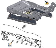
Begin with the design criteria and create components that meet those criteria. Designers list known parameters and create an engineering layout. The layout can be a 2D design that evolves throughout the design process as shown in the following image.
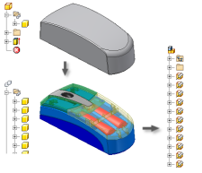
The layout can also be a 3D design created from a single multi-body part file as shown in the following image. This method uses 3D part modeling commands to create a unified design that is controlled by a single part.
The layout can include contextual items such as the walls and floor where an assembly will stand, machinery that feeds into or receives output from the assembly design, and other fixed data. Other criteria such as mechanistic characteristics can also be included in the layout. You can sketch the layout in a part file, and then place it in the assembly file. Develop sketches into features as the design evolves.
Designed components are unique to this assembly, but standard parts such as bolts, pins, or rods can also be used. Changing one part can cause changes to several other parts that are adjacent or connected to it.
The final assembly is a collection of interrelated parts that are uniquely designed to solve the current design problem.
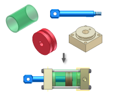
Bottom-up
Place existing parts and subassemblies into an assembly file, positioning components by applying assembly constraints, such as mate and flush. If possible, place the components in the order in which they would be assembled in manufacturing.
Unless component parts are built from adaptive features in their part files, they might not fit the requirements of an assembly design. You can place such a part in an assembly and then make the part adaptive in the assembly context. The part resizes in the current design when you constrain its features to other components.
If you want all underconstrained features to adapt when positioned by assembly constraints, designate a subassembly as adaptive. When a part in the subassembly is constrained to fixed geometry, its features resize as needed.
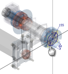
Middle-out
Usually, you begin with some existing components and design other parts as required. Analyze the design intent, and then insert or create the grounded (base) component . As you develop the assembly, place existing components or create new ones in place, as required.
If new parts or subassemblies are likely to be used in other assemblies, consider designating them as adaptive. To change size or position of some features, consider leaving them undimensioned. The feature can then change size and shape when constrained to other components in an assembly. Because changes to a part are saved in the part file, to maintain more than one version of a part, save the parts with different file names.


.gif)
0 comments:
Post a Comment