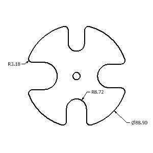
Selamat datang di blok nya wong mesin SMK Negeri 1 Blitar

Silahkan mengambil manfaat yang sebanyak banyaknya dari blok ini untuk percepatan kemajuan pendidikan SMK di indonesia....

Selamat datang di blok nya wong mesin SMK Negeri 1 Blitar

Silahkan mengambil manfaat yang sebanyak banyaknya dari blok ini untuk percepatan kemajuan pendidikan SMK di indonesia....

Selamat datang di blok nya wong mesin SMK Negeri 1 Blitar

Silahkan mengambil manfaat yang sebanyak banyaknya dari blok ini untuk percepatan kemajuan pendidikan SMK di indonesia....

Selamat datang di blok nya wong mesin SMK Negeri 1 Blitar

Silahkan mengambil manfaat yang sebanyak banyaknya dari blok ini untuk percepatan kemajuan pendidikan SMK di indonesia....

Selamat datang di blok nya wong mesin SMK Negeri 1 Blitar

Silahkan mengambil manfaat yang sebanyak banyaknya dari blok ini untuk percepatan kemajuan pendidikan SMK di indonesia....

Selamat datang di blok nya wong mesin SMK Negeri 1 Blitar

Silahkan mengambil manfaat yang sebanyak banyaknya dari blok ini untuk percepatan kemajuan pendidikan SMK di indonesia....

Selamat datang di blok nya wong mesin SMK Negeri 1 Blitar

Silahkan mengambil manfaat yang sebanyak banyaknya dari blok ini untuk percepatan kemajuan pendidikan SMK di indonesia....

Selamat datang di blok nya wong mesin SMK Negeri 1 Blitar

Silahkan mengambil manfaat yang sebanyak banyaknya dari blok ini untuk percepatan kemajuan pendidikan SMK di indonesia....

Selamat datang di blok nya wong mesin SMK Negeri 1 Blitar

Silahkan mengambil manfaat yang sebanyak banyaknya dari blok ini untuk percepatan kemajuan pendidikan SMK di indonesia....

Selamat datang di blok nya wong mesin SMK Negeri 1 Blitar

Silahkan mengambil manfaat yang sebanyak banyaknya dari blok ini untuk percepatan kemajuan pendidikan SMK di indonesia....

Selamat datang di blok nya wong mesin SMK Negeri 1 Blitar

Silahkan mengambil manfaat yang sebanyak banyaknya dari blok ini untuk percepatan kemajuan pendidikan SMK di indonesia....

Wednesday, April 30, 2014

Export parts and more


You can export Autodesk Inventor parts and assemblies to other CAD system formats. The export operation does not maintain associativity with the Autodesk Inventor file. As a result, changes to the Autodesk Inventor file after the export operation do not affect the exported part or assembly. Likewise, changes to the exported part or assembly do not affect the Autodesk Inventor file.
The objective of the Autodesk Inventor export operation, for part and assembly files, is to create files as if they were created in the native CAD system format. As a result, use of the exported files in the native CAD system is typically seamless. However, take care before using the exported files since all features may not export exactly as they appear.

Publish designs


Digital prototype data can be published to various formats in Inventor. This data can include parts, assemblies, drawings, in any combination, depending on the file type selected. To publish, use the Save Copy As command and select a file type, or use the various Export commands. Supported file types include:
  • 2D and 3D DWF files
  • CAD file formats including Parasolid®, Pro/ENGINEER®, and STEP
  • 2D PDF files
  • Image files including BMP, JPEG, PNG, or TIFF
DWF files are an Autodesk file type that can contain 3D data, 2D data, and bill of materials information. You can view DWF files in Autodesk® Design Review, a free download that contains commands to view, print, and mark up DWF files.


Files published to DWF format

Viewing and sharing data is an important tool when communicating with vendors, customers, and marketing.
Autodesk Digital Prototype data can be published in DWF (.dwf or .dwfx) format and viewed using Autodesk Design Review. You can also view DWFx drawing content natively in Internet Explorer 7.
Note: Only 2D graphics display when viewing DWFx files in Internet Explorer 7.
Anyone can use published DWF files, even if they do not have Autodesk Inventor installed. You can open and view the highly compressed files quickly, and you can share them through email.
Publishing from Autodesk Inventor creates DWF files that maintain design data such as line weights, scale, and mass properties for 2D and 3D files and can be in one file.
When you publish the file, use the Autodesk Design Review to view and print it.
Note: To publish a large file and output a small file size, choose the Express Option and disabling Enable measure in the Publish dialog box. The quality of the resolution of the output file diminishes, but the process is fast. Using the other publishing options (Complete or Custom) can increase the time it takes to create the DWF and also generate a larger file size and improve the visual quality.
Tip: You may not need (or want) to share the full 3D model. Use the 2D Snapshot option in Express mode to publish the current view of an assembly, part, or presentation (*.iam, *.ipt, *.ipn) as a 2D DWF.
Note: The program identifies quality difference only in 3D model publishing. Publishing options do not affect the quality of a 2D drawing. For 3D models, the measurement on the file published using Express mode is less accurate than the measurement on a file published using Custom/Complete mode. In most cases, the quality of publishing result looks almost the same between Express mode and Custom/Complete mode. Edges of 3D model are the only exception.

About Hyperlinks

Hyperlinks guide you through published sheets and their content in the DWF file. The program adds hyperlinks to the sheets to connect them to the associate views, drawings, 3D models, or other data such as parts lists or bills of materials.
For example, a geometry hyperlink on a 2D sheet can link to related views and back, even when on other sheets. Views also can have links right to the 3D model all within the same DWF file.
When you move the cursor in the canvas area and the hyperlink is present, the cursor changes. A tooltip appears showing the destination of a hyperlink connection and instructions for following it. Clicking a hyperlink displays the linked 2D content.
Note: In the viewer, you cannot change the hyperlinks.
In the Views palette of the Design Review, click the Published views item to display the list of views, published title blocks, tables, parts list, and revision tables. Click to display the item in the canvas area of the viewer.
Objects containing hyperlinks:
  • drawing views - section geometry views, auxiliary view geometry to the appropriate views. View labels contain links back to the parent view. Includes links across sheets.
  • Drawing tables - hole tables, parts lists, revision tables.
    Published tables contain links to appropriate objects. Hole tables are linked to the hole tags, parts lists are linked to the balloon callouts, and review tables are linked to the revision callouts.
  • The Bill of Materials cross-highlights the components in the viewers canvas.
  • Revision tables - Autodesk Inventor provides a link from the revision table to the revision tag that helps you to find the change described in the table. Click the Revision History item in the Views palette of the Design Review to display the revision table. Click the revision tag to navigate back to the revision tables.

Drawing Standart & How Custom It


Each drawing stores styles that control the default appearance of drawing annotations. The Drawing Styles.idw document includes styles corresponding to the ISO standard. The styles were copied to the document when it was created from the ISO template.
In addition to the local document styles, styles from the style library are available in the drawing. The style library can store all the styles your company uses. To reduce document size, there are more styles in the style library than in a drawing.
Review styles available in the Drawing Styles.idw document:
  1. Click Manage tab  Styles and Standards panel  Styles Editor  .
    The Style and Standard Editor dialog box displays. In the browser panel on the left, styles sorted by types are listed. In the right panel, details for an item selected in the browser panel are displayed.
  2. To review all available styles, select All Styles from the Filter list .
    In the browser, the Standard list displays all standards available in the style library. The Default Standard (ISO) is marked bold to indicate the standard is currently active in the drawing.
    The active standard defines a set of annotation styles used in the drawing. In addition, it contains settings for views, text, hatches, and object defaults.
  3. To create a custom Standard style, select Default Standard (ISO), and click New…
  4. In the New Local Style dialog box, in Name, enter Modified Standard (ISO), and click OK.
    A new standard based on the Default Standard (ISO) is added to browser under the Standard node.
  5. To activate the custom standard, right-click the Modified Standard (ISO), and select Active.
  6. Click the Dimension node in the browser. Then review a list of available dimension styles in the Dimension Style panel.
    Notice that:
    • Location of styles stored in the drawing is Both, and location of styles stored in the style library is Library.
    • Styles used in the drawing display Yes in the In Use column.
    • The Changes column displays No for all styles.
  7. Select Local Styles from the Filter list. Then review dimension styles stored in the drawing file.

Types of Drawing Annotations


General Dimensions
You can create general dimensions in orthographic or isometric views. The geometry you select determines the dimension type and the options available in the context menu.
You can override the dimension text, which does not affect the model geometry.
You can change the dimension precision and tolerance, edit the leader and arrowheads, or modify the content of dimension text.
Baseline Dimensions and Baseline Dimension Sets
Creates multiple dimensions that display the orthogonal distance between the origin (base line) and selected edges or points. The first edge or point selected is the origin geometry. You can create individual dimensions or a dimension set.
Ordinate Dimensions and Ordinate Dimension Set
Creates multiple ordinate dimensions in a single process. Ordinate dimensions automatically align as you place them. If dimension text overlaps, you can modify the dimension position or dimension style. You can create individual dimensions or a dimension set.
Retrieve Dimensions
Displays all model dimensions, or only dimensions related to selected parts or features. You select the dimensions to maintain in the drawing view.
Only model dimensions parallel to the view plane are available.
Model dimensions can be modified to manipulate the part file.
Center Marks
Center marks are added to the selected arc or circle. Center mark extension lines are automatically sized to fit the geometry.
Center marks can be added individually or using the automated centerlines command.
Centerlines
Creates centerlines for selected edges, at the midpoint for lines, or at the center point of arcs or circles. Creates a circular centerline when features form a circular pattern.
Autodesk Inventor supports three types of centerlines: bisector, centered pattern, and axial.
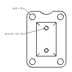
Hole/Thread Notes
Hole or thread notes display the information from hole, thread, and cylindrical cut extrusion features on a model. The style of the hole note varies depending on the type of feature selected.
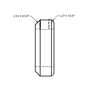
Chamfer Notes
Chamfer notes contain distance and angle measurements for selected model edges or sketched lines.
You can attach chamfer notes to angled edges in views and sketches. A chamfer edge and reference edge from different bodies, models, or sketches, must be part of the same view.
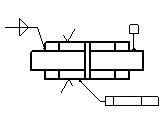
Symbols
Various types of symbols are available: surface texture, welding, feature control frame, feature identifier, datum target, and datum identifier symbols. Symbols are created with or without a leader.
User-defined or sketched symbols are defined in the Drawing Resources and are placed like standard symbols. They are used to define custom symbols that are not available in Autodesk Inventor.
Bend Notes
A bend not adds fabricating information to sheet metal bend, contour roll, and cosmetic centerlines. Bend notes can be added to flat pattern views of sheet metal parts.
A bend note is associated with the selected bend centerline. The default placement of the bend note is above the selected bend centerline. It constrains the bend text to the midpoint of the centerline and offsets by the Origin Offset value from the Dimension Style.
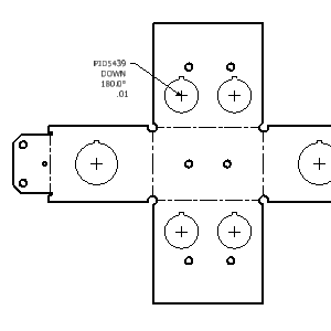
Punch Notes
A punch note includes data related to the punch feature: for example the punch ID, angle, direction, depth, quantity note, and so on.
Punch notes can be added to flat pattern views of sheet metal parts.
Caterpillars
Weld caterpillars are used to denote weld features in 2D views. You can add weld caterpillars manually using the Caterpillar command. Add them automatically from weld features using Get Model Annotations > Get Weld Annotations on the context menu.
End Fills
End fills are used to represent the filled region indicating the end of a weld bead. You can add them manually using the End Fill command or automatically from weldment models using Get Model Annotations > Get Weld Annotations.
Change end fill appearance through object properties.
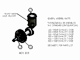
Balloons
Balloons are annotation tags that identify items listed in a parts list. Balloons can be placed individually or automatically for all components in a drawing view. You can add balloons to a custom part after it is added to the parts list.
The balloon shape and value can be overridden using Edit Balloon on the context menu. You can combine balloons to use a single leader using the attach balloon options on the context menu.
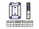
Parts lists
Parts lists display data saved in the assembly bill of materials. The parts list can be modified to include different columns or overridden values. The bill of material data can be modified from the drawing file or the assembly file.
Custom parts can be added to the parts list to include items that are not modeled such as paint or grease.
Tables
You can create a general, configuration, or bend table.
A general table can have a default number of rows and columns, or you can customize its size. The general table can reference external data from .xls.xlsx, or .csv files, or you can enter any other type of data you need.
In drawings of iParts and iAssemblies, configuration table rows represent the members of the factory. You can specify the columns to include in the configuration table, such as exclusion status and values that are different among members.
A bend table is created if a sheet metal part is the source of the table. Bend tables contain bend information such as angle and radius.
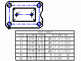
Hole Tables
Hole tables show the size and location of the hole features in a model. When a hole table is added, each individual hole receives a hole tag and a corresponding row is added to the table.
You can also add center marks, punch features, and cylindrical cut extrusion to a hole table by editing the table.
Revision Tables and Tags
Revision tables include information about design changes. Revision tables can be created for the entire drawing file or a single sheet.
A revision tag marks an object changed by design revisions. The default revision level for the tag is the latest revision in the table. The revision level of the tag can be changed using the context menu.
Text or Leader Text
Use Text to add general notes to a drawing. General notes are not attached to any view, symbol, or other object in the drawing.
Use Leader Text to add notes to objects in a drawing. If you attach the leader line to geometry in a view, the note is moved or deleted when the view is moved or deleted.

Exploded views


Exploded views describe assemblies by moving components out from their assembled position. You can use exploded views to balloon an assembly using item numbers found in a parts list or bill of material. You create exploded views by using a combination of assembly (.iam), presentation (.ipn), and drawing (.idw, .dwg) files. A view of the assembly is created in the presentation file, and the components are repositioned in the view. Drawing views are then generated from the presentation file.

Types of drawing files


Autodesk Inventor supports IDW and DWG file types for drawings. Both file types produce identical drawings. IDW files are the native Inventor format. You can open them only in Inventor or Inventor View. This file type results in smaller file sizes.
The DWG file type is native to AutoCAD®. You can open DWG files in AutoCAD, Inventor, or DWG TrueView. If you create data using Inventor in a DWG file, you can modify the data only with Inventor. If you create data using AutoCAD in a DWG file, you can modify the data only with AutoCAD. If a downstream consumer of your Inventor data needs a DWG file, consider using DWG files as the default in Inventor.

DWG translation

When you import an AutoCAD, Mechanical Desktop, or Autodesk Inventor Fusion file in Autodesk Inventor, or export an Autodesk Inventor drawing to AutoCAD format, specify various settings for the translated files.
To make the process more efficient, you can save a group of settings as a configuration, and use the configuration to set the translation options automatically. You can save as many configurations as needed. Configuration settings are saved in a file with an .ini extension.
To save a configuration, set the options for opening or saving a DWG (.dwg) file. In the final dialog box, provide a file name and click the Save Configuration before clicking Finish.
To use an existing configuration, click Browse in the DWG/DXF File Wizard dialog box, and then find the appropriate configuration file. When you specify a configuration file, you do not need to select any other options.

Note on opening DWG files

You can set the default behavior for an AutoCAD DWG in the Drawing tab of Application Options. Use the drop-down under Non-Inventor DWG file to specify Open or Import.
If you do not require AutoCAD objects translated into Autodesk Inventor objects, you can directly open any AutoCAD DWG (.dwg) file inAutodesk Inventor. You can view, plot, and measure the file contents. Objects display exactly as they do in AutoCAD. In addition, all the AutoCAD data is selectable for copy and paste. You can open an AutoCAD DWG file in Autodesk Inventor, and then copy and paste AutoCAD entities into any Autodesk Inventor sketch.

Drawing View Operations


Break
An operation that reduces the size of a model by removing or “breaking” irrelevant portions. Create a break in a view if the component view exceeds the length of the drawing, or contains large areas of nondescript geometry. An example is the center portion of a shaft.
Dimensions that span the break reflect the true length.
Break Out
An operation that removes a defined area of material to expose obscured parts or features in an existing drawing view. The parent view must have an associated sketch that contains the profile defining the break out boundary.
Crop
An operation that provides control over the view boundary in an existing drawing view. The clipping boundary can be a rectangle or circle you create during the command, or a closed profile you select from a sketch.
Slice
An operation that produces a zero-depth section from an existing drawing view. You perform the Slice operation in a selected target view. The slice lines are defined in a sketch associated to a different view.