
Assembly (.iam) Files
In Autodesk Inventor, you place components that act as a single functional unit into an assembly document.Assembly constraints define the relative position these components occupy with respect to each other. An example is the axis of a shaft aligning with a hole in a different component.
When you create or open an assembly file, you are in the assembly environment. Assembly commands manipulate whole subassemblies and assemblies. You can group parts that function together as a single unit and then insert the subassembly into another assembly.
You can insert parts into an assembly or use sketch and part commands to create parts in the context of an assembly. During these operations, all other components in the assembly are visible.
To complete a model, you can create assembly features that affect multiple components, such as holes that pass through multiple parts. Assembly features often describe specific manufacturing processes such as post-machining.
The assembly browser is a convenient way to activate components you want to edit. Use the browser to edit sketches, features, and constraints, turn component visibility on and off, and do other tasks. In the following image of an assembly, two of the components display an icon indicating they are part of a contact set. Components that belong to a contact set behave as they would in the physical world.
Presentation (.ipn) Files
Presentation files are a multi-purpose file type. Use a presentation file to:
- Create an exploded view of an assembly to use in a drawing file.
- Create an animation which shows the step by step assembly order. The animation can contain view changes and the visibility state of components at each step in the assembly process. You can save the animation to a .wmv or .avi file format.

Drawing (.idw, .dwg) Files
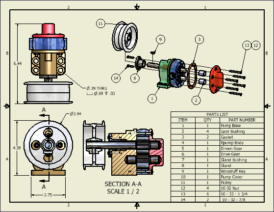
After you create a model, you can create a drawing to document your design. In a drawing, you place views of a model on one or more drawing sheets. Then you add dimensions and other drawing annotations to document the model.
A drawing that documents an assembly can contain an automated parts list and item balloons in addition to the required views.
The templates to use as the starting point for your drawings have the standard drawing file extension (.idw, .dwg).
Autodesk Inventor maintains links between components and drawings, so you can create a drawing at any time during the creation of a component. By default, the drawing updates automatically when you edit the component. However, it is a good idea to wait until a component design is nearly complete before you create a drawing. Edit the drawing details (to add or delete dimensions or views, or to change the locations of notes and balloons) to reflect the revisions.

.gif)
0 comments:
Post a Comment